

1/650 scale U.S.S. Excelsior (commission)
- Cascade Starships
- Jun 21
- 20 min read


Another build breakdown, this time of my recently completed 1/650 scale U.S.S. Excelsior! This will go into every stage of the build process, unique techniques used, and of course a detailed explanation behind the reconstruction of the complex paint job on the original studio model. If you're looking for the .SVG files of the aztec patterns, the zip file can be found right below.
PLEASE NOTE: These files are meant for the Excelsior! If you are wanting to do the Enterprise B or Lakota, use your reference images to see what is shared between these ships and what is different.
CLICK HERE TO SKIP TO THE PAINT BREAKDOWN
This build is based around the Helios Models & Lighting resin printed model kit. This build took 8 months and 220 hours. You can find the finished studio photography for this build here.
Being a commissioned build, the first stage is finding out what the client wants out of the project, and planning from there. Fortunately, the client was very clear: just make it look good. Okay! Let's see what this kit needs.

The kit arrived looking great! I had some issues with parts which I will get into later. Additionally, being a resin printed kit, this needed an internal support structure to hold the weight of the kit, to keep parts from sagging, and transfer the load into the display rod. One cool thing about this Helios kit is that it comes with metal printed pylons! Larger scales of the kit come with a factory made support structure, but this size does not. I guess they determined it wasn't necessary at this size. I tested how reactive the material is to heat and it basically turns into play-doh, so I couldn't trust that decision.
I knew I couldn't bear to wrap this lovely kit in waterslide decals for the aztec patterning. Fortunately, my friend Hagen Miller had just finished his build of the kit and painted the azteccing himself! He broke down the specifics of how this kit was painted, what patterns were used where, and generally what techniques were used all over the model. This allowed me to then come back around from the beginning with fresh eyes and try my best to fully understand and recreate each layer on the model and tweak some of the things Hagen made to be purposeful to my needs for the kit.
I wanted the registry and pinstriping decals to be as high quality as possible, so I hit up my friend Wiley's Model Decals who was more than happy to create custom waterslides for me.
In terms of lighting the Excelsior, the ship is generally a little boring. It barely has an upper saucer spotlight, the spotlight on the secondary hull pennant makes little sense, and it is missing some of the light features that the beautiful Enterprise has, so I spoke with my client and we came up with a plan for extra spotlights to more align it with the Refit. The nacelles already have holes for spotlights in the same spot as the Refit, so it was easy to plan out the pennant spotlight and the spotlight that hits the aft saucer rim. Then we added a spotlight that shines down the outboard side of the pylons. Additional spotlights were considered but disregarded later.
Additional details were decided upon, like docking ports, but I'll get into that later.
Okay, let's start getting into the build.
The factory that this kit is printed at sands their own prints before shipping it. This is GREAT most of the time as parts arrive smooth and feeling good. I can attest that the factory has refined their processes since purchasing this kit, but when I first got the Excelsior, every single part was over-sanded. Most things I could bring back to life myself, but I requested replacement parts for the things I could not.
The upper half of the pylons, the neck, the upper saucer, and the secondary hull were things I needed replacements of. I could not bring back the ribs of the neck and pylons without extensive labor, and the panel lines of the secondary hull were entirely gone. Helios was very responsive in providing replacement parts and I was pleased with the second round of parts.

The rest of the parts just had sanded down panels, which are panels that are meant to be raised and sharp, but were delivered super rounded off or gone altogether. These can easily be replaced with cut styrene.

So I took some measurements and made some guesswork about proportions before putting my vinyl cutter to work. Vinyl cutter? It's not called a styrene cutter, BUT styrene is very receptive to being scored and snaps cleanly. All I had to do was tell it to use minimum blade depth and a tiny bit of force, then I could snap the panels away from each other. This, of course, worked great! I cut enough panels to build 3 of these kits. The .SVG for this, scaled to 1/650, can be found in the .ZIP file above. You are free to tweak this to taste! Wish I could tell ya what thickness sheet I used, use whatever feels right. The sheet I ended up using, I had to knock down the panels a little anyway.

To apply them I just used some standard CA glue. Some of the pieces were small enough that they had to be picked up with a hobby knife.

The same goes for the lower saucer. I sanded away what remained of the printed panels and re-scribed many of the panel lines that were too shallow for my liking. The panel lines didn't come out the straightest but it all goes away with the busy paint job. One other thing that didn't get photographed was using Solarez doming UV resin to replace the phaser turrets. The resin sticks to wherever you put it but pulls itself into a very round dome in the process, making it perfect for this, and capping off navigational lights.
While I was at it, I spoke with the client and we decided that the Excelsior was missing something. Sure, she has 2 shuttle bays/cargo bays, but the lack of docking ports generally doesn't make sense. So I had a friend of mine print the Modelwerks 1/350 refit docking ports at a percentage of the size to be at least close to 1/650 scale. It was a little difficult finding a spot on both sides due to the asymmetry of the panel lines and windows, but I got something good eventually.
One detail completely omitted from the printed kit is this ribbing detail on the inside walls of the large recessed panels on the ventral side. These were made with leftover Photoetching that ILM had on hand, so I'm going to do the same!
So, I took some 1/700 scale photoetch ladders and railings for naval watercraft and glued them around the rim in the same fashion as the studio model.

Next is planning some of the lighting and modifying the kit for some of the light features I wanted. Specifically here, the spotlights! The lower saucer was easy, as I focused a 0605 SMD with a piece of styrene sheet embedded into the planetary sensor. The upper saucer was harder. I tried very hard to do it legitimately but the size of the saucer and how fast the saucer drops away means the light doesn't reach very far. SO I cheated on just this one and went with a Raytheon effect which I will describe later, but you can see some mockups of it below.
Taking a break from spotlights, I wanted to work on the support structure for the kit. As stated above, the kit is made out of resin, and resin gets super soft when warm. I wanted to ensure the model didn't warp or sag anywhere over time and the best way to do that is create a way that the weight of the model is distributed evenly instead of hitting every joint of the kit on the way down to the mounting point. Bill Krause is a good example of these structures and I recommend you check him out. Like him, mine will be made with brass tubing joined together with silver solder.
I spoke with the creator of the 3D files for this kit and got some orthographic section views of the kit to plan out how the brass gets routed through the kit. I had a little bit of fun with the drafting, bringing my work experience and education to this build.

Fortunately for me, a piece of brass at a solid 45 degree angle can go from the mounting hole to the saucer just barely missing the neck and deflector alcove. I designed it so the cantilever force downward from the saucer goes to the mounting point and back up to push into the back horizontal beams that hold up the secondary hull. The neck transfer has 2 attachment points for the saucer cross to help with any rotation around the first attachment point at the front.

I made 2 of these to go on either side of the central mounting rod. I realized that the back horizontal beams don't fit around the locating tabs at the aft of the secondary hull, so I cut them shorter and made them go around. Each aft horizontal beam has 2 attachment points for the same moment forces as the saucer.
Due to my preference for assembling this model, the saucer cross had to be removable, so I used telescoping brass tubing to slide inside each other. The ends of the cross had to later be cut shorter and at an angle due to the interior space inside the saucer. A square styrene rod is used to ensure the structure sits in the same spot every time during test fitting so no additional surprises occur. It also provides additional gluing surfaces to adhere the structure to.
I'll admit, this was a little more complicated than the kit deserved but I didn't want to take any chances and I wanted to do what I knew I could build. Something like this is super hard to teach so I've done the best I can to describe what I did.
You may have noticed that this structure does not include the nacelles. The kit is pretty cool in that it includes metal printed pylons with purchase, so there's no concern about pylon sagging or twisting. However, the nacelles have no internal support at all and are mounted very forward with a lot of weight hanging out the back. So I epoxied 1/4" square brass tubing down the length of the inside of the nacelle.
More spotlights! This time the nacelles were a little harder to do due to how far away the front of the nacelles are from what I want to light up. I used telescoping round brass tube to create something a 3mm LED can fit in and I can add smaller brass tube to focus the light. It took a lot of trial, error, and dabs of super glue to hold it in place. You may notice there are 2 holes in each spot on the nacelle. I could only put a LED in one side due to clearances. I left the second one open to catch some internal light to make it seem a little like both sides light up. The brass tubes were grinded flush with the surface and putty to seal it up fully. Some Aves epoxy putty was used on the inside to support the tubing a little more.
This happened during a transition between 2 locations so the pictures will start looking different.
And now the other nacelle at my new place!
The pylon spotlights mentioned earlier are done with an 0605 SMD and a tiny hole drilled into the bottom of the nacelle. The material inside is very thick, so material was carved away inside until the light was focused enough to create the desired shape. With wiring done, a test and fit was made and the nacelles were epoxied together.
Moving onto the secondary hull! Another part that was sanded a little too much but I forgot during the initial panel replacement run was the shuttle bay doors/hood. This time I cut the pieces manually with the chopper shown below. Pieces were attached the same way as before.
Lighting the secondary hull was pretty cool. First, I did lightblocking on the inside with primer and black paint, then painting everything in flat white to diffuse and distribute the light to make it fuller. The first thing I wanted to try was adding variation to the windows with some window transparencies. The windows are too small to do anything really meaningful, but putting something behind them helps a ton at least in person. Then the large cargo bay needed to be lit. Since I wanted to program a startup sequence, I needed to isolate some of these light sources. A light box was built to sit atop of and behind the cargo bay to house the Ice Blue COB tape. White COB tape is glued to the top plate of the secondary hull to shine downward. Styrene sheet bounces the light toward the windows
The deflector dish was really fun to get right. Since this is the NCC Excelsior, it needed a white hotspot that softly transitions to blue at the edges. The light source was isolated with a cap to a Vallejo paint bottle. A 3mm white LED is mounted to some styrene tube to bring it closer to the surface to make that white hotspot. The dish piece itself was lightly airbrushed around the edges with clear blue to get that blue tint.
Doing the "spokes" felt like it was going to be impossible because they have to be opaque and straight. Rather than painting them, OR building them with styrene, I pulled out my vinyl cutter and cut the spokes out of white permanent vinyl.
Now, power has to get to the model somehow. I used a 12 pin 1b sized Lemo plug to be able to quickly lift the model off the display stand without worrying about the wires. I have 7 wires running through the model, 6 positive leads and 1 common ground. This will be important later. I epoxied the female end to the support structure after wiring it. I had to grind the threads down a little to make it fit. The male end of the connector can be disassembled with threads, so I put the female end threads of the male end of the connector (phew) into the main display rod with epoxy. So now I can easily remove the connector from the display rod if needed and have a stable quick disconnect for the model.
This now means that the support structure can be permanently attached to the model!
Here's why the saucer cross members had to be removable. I wouldn't have been able to slide this top plate over it otherwise!

Light test before everything gets sealed
Now no matter how much lightblocking you do inside, you should always expect to do more from the outside. This was done with more primer and more flat black paint.

I can now epoxy the nacelles to the pylons!
Last hull section to do: the saucer. Now, we already figured out the spotlights so that was easy to figure out on the lower saucer. The portholes that face directly downward are weird to get light to, so I decided to place styrene sheet at an angle above them that will bounce the light downward and evenly into the windows. And that is all on the lower saucer.
On the original studio model, there was a mesh at each opening of the planetary sensor. So I took some Hasegawa modelling mesh and cut it to the appropriate size for each opening.
The NX-2000 version of the Excelsior had glowing blue rings on the planetary sensor. This was a neat little addition of life so I masked them off before I lightblocked. The blue comes from painting the inside of the sensor clear blue and using some internal light to make it glow.
Then the lower saucer can be epoxied to the structure! The only image I have of this is a comparison with a nacelle to a 1/650 scale Ambassador class model.

The upper saucer was more complex. It contains all of the windows, the impulse engines, the strobe lights, etc. Its got everything.
The first thing to get right is the spotlight. Now, if you recall, the upper saucer can't have a normal spotlight where a light on the outside shines on the outside of the plastic. So I had to use something called a "raytheon" effect. This is a technique that allows you to make spotlights by shining light from inside the model THROUGH the plastic in the shape of what a spotlight would normally look like.
This is risky to do. It is very easy to make look very bad especially on a model where you're going to have multiple layers of paint on top.
My tips for this are to:
Place a light on the inside where the normal outside light would be. This creates a more natural hotspot.
Feather the inside edges with grey paint. It won't completely lightblock and will soften the edge. Do this to the edge furthest away from the light source. The closer you are, the sharper the line should be.
Make any panel lines dark. These are recessed and would normally be in shadow. My choice for doing this is scribing the panel lines deeper, priming and lightblocking the area, and then sand away the paint leaving behind the stuff inside the panel lines. This prevents the panel lines from accidentally being brighter which will absolutely ruin the whole look.
To start, I drew the shape I would like it to be on some tape on the model. I even played with using a real light to see what would be natural. I scanned this and drew over it on my computer to create a vinyl mask to use on the inside when I lightblocked.
A piece of sheet styrene serves as a platform to host COB led tape which will light the upper deck windows.
And then the 30 billion windows along the rim each need a source of light. Red COB is attached underneath the impulse engine openings with some sheet styrene to redirect the light backward. The light for this was dimmed with a resistor later.
Glue it together, some putty, primer, and sanding, and that's basically the whole model assembled and glued together!
Except for the nacelles. To keep things easy I decided they would be the last piece of the hull epoxied together. To facilitate this, I crimped together a custom 5 pin plug so I can easily make sure everything still works with no hassle. There are some various things here and there left off but it's an easy job for CA glue when the time comes.

Now, the paintwork:
"Aztec" paneling or patterning is a reference to a nickname that was given to the Enterprise Refit's distinct paint job that turns the very large hull into something that looks like it is made up of smaller panels. Painting panels like this is one of many techniques used to make scale models look bigger than they are. Something like Star Wars often uses shading and weathering techniques to make something feel more real, and therefore larger than a tiny model.

Things in real life aren't made of one big piece formed to the complete shape. Everything is made of smaller pieces. The barge below is made up of a bunch of panels riveted or welded together. Not a single one looks the same. When 2 sheets of metal are put side by side, the grain or finished texture might reflect the light differently than the other (specularity). An example of this used in Star Trek is the picture posted above. Even if they're painted, you can see they all aren't tangent to each other because of how they sit over the internal frame.
Now once you start getting into sci-fi stuff with magic materials, anything is possible. But the point I wanted to make is that these aspects of real world structures and materials is the basis for this technique that Star Trek uses for its ships, even if a little exaggerated at times.
Here's a little context about the environment the original Excelsior class studio model was painted in: Industrial Light and Magic (ILM) is very good at using whatever is on-hand, and reusing things created for other projects. In addition to this, they are almost always on a time crunch.
ILM built many models for Star Trek III: The Search for Spock, namely the Excelsior and Earth Spacedock studio models. I bring this up because both models use the same patterns for their paint job. We know this from this image below:

This is from a propstore auction. These patterns (plus a couple loose extra ones) are used on both the Earth Spacedock and the Excelsior. You can see some of the patterns in the pictures below. These are photoetch frisket masks.
Here's a neat piece of trivia: the rectangular patterns in the upper right are also used on the Death Star!
Once this was discovered (thanks Hagen), it was VERY easy to see what patterns were used where. (and to hallucinate other patterns that aren't lol).
I'd like to say my paint job is the closest that is currently out there, but I know there are things that I definitely missed which means there are things I missed and don't know about.
This isn't meant to be a step-by-step. Just to give some context and skills so you can do it yourself and maybe even be even more accurate than mine!
IMPORTANT
The basis for painting this model in almost all sections is by basecoating in very lightly misted silver. I'm talking so light that you shouldn't be able to see it when you're done. I used Alclad metallics due to their super fine mica powder and thinned them further with lacquer thinner. The lower saucer does not get this (a little), and the upper saucer uses gloss for its shine instead.
OKAY with all that context I think we can begin.
I think the easiest part of the hull to get a feel of this for is the secondary hull sidewalls. There's one distinct pattern in the front and the rest is a little indistinguishable. So first like I said above, the model is coated in a VERY LIGHT MIST OF SILVER. Once this is done, white paint is sprayed through a flattened version of one of the patterns. This is moved side to side and down the decks.
What this does is create slightly lighter painted panels over a slightly darker background. When the light hits it a certain way, it flips. The reflectivity of the silver makes it brighter than the flat white, and makes the flat white look dark. You don't have to, nor shouldn't, use the full mask. Allow overlap, allow overspray, and don't be afraid to restart.
A small wedge version of the pattern is quite useful for the bow. Also note the distinct pattern on the very front.
That was simple right? Lets go to the next stage. Here is where we start getting into the idea of "burying" colors. The nacelles have scattered blue and grey panels that are visibly underneath many layers of white paneling. So first add that silver layer, then use masking tape to cover up parts of the masks to spray one of your blue colors through.
Now use the same patterns as the secondary hull to paint thinned flat white paint through. You don't want it to be opaque until your 5th or 6th layer (a rough guess).
Click through to see each layer. I wanted to make sure you can look at these very close without taking forever to scroll through.
The pylons have a pretty distinct pattern, so same as before with the silver basecoat and flat white. The "pontoon" in the center was painted with a wedge shaped version of the patterns.
I'm going to skip a couple steps because its standard paintwork on the rest of this part.
Same rough story on the tailfin. One specific pattern is used around the opening of the cargo bay. everything else is aztecced with what is nicknamed the "railroad tracks" pattern. Cut these as small as your machine can, and then do a couple more a little bit larger. Misted silver over white, mist white through the mask.
The center blue stripe is the inverse of the pattern so I painted the blue, masked off a strip of white, then painted the blue through the mask again. There's a pattern in the ZIP file at the beginning that lets you cheat 80% of the pattern on the large blue area, but you still need to supplement with additional masked off portions of the railroad tracks in both white and grey.


Same for this upper deck. There's a mask in the files that will get you 80% there but you'll have to supplement with additional railroad tracks. The silver painted here is fully opaque for the main pattern and a little lighter for the secondary.
The shuttle bay hood is similar to the nacelles, but with red and grey. This is the only part of the model that uses red in its azteccing. If you look at reference images you can see some distinct patterns running in straight lines, but I couldn't parse how it was done.
Annddd the secondary hull is done.
The saucer takes a lot of what we learned before and combines it all!
With both halves of the saucer I can only give you precisely what I saw and then "blend it with a bunch of random layers".
The lower saucer was pretty easy to see what pattern is underneath anything so I started with that.
You could paint it this way or invert the mask and paint the grey and blue through it, rather than white over the blue and grey. It doesn't matter much. You may note the mask is only large enough to get the inside part of the saucer. The outside ring doesn't have to fit as precisely, so you can use the Upper Saucer version of the mask.
Then add these very distinct shapes in the pattern below. PLEASE USE REFERENCE IMAGES AND NOT JUST ME.
In the wedges that only have grey, paint silver through the pattern below.
There's one distinct pattern that goes over the wedges that contain blue. The pattern is just a cropped version of another pattern that was created for convenience. The image of my WIP model has a couple extra layers on it that I attached for reference.
In-between the blue wedges of the outer ring is grey through the pattern shown below.

Then keep layering with the same patterns, mask off sections, shift the mask around, and paint with thinned flat white until it looks right!
Here is a comparison with the studio model. I suggest you compare yours because I'm sure you can see things that you would do differently than me!
There's a pattern in the files that makes this part easy but you can scale and crop the main pattern this comes from to taste.
Aaaand that's the lower saucer done!
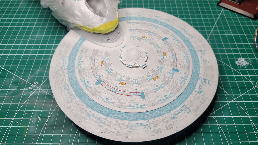
The upper saucer is a little funkier. The base pattern is very simple, the tiny distinct shapes are easy, but the subsequent blending layers are super difficult to parse but as long as you add enough to knock down the underlying pattern, it will look great.
FIRST PAINT THE SAUCER WITH GLOSS. Then, you can continue with everything else. The gloss will peek through all of the layers and will look great.
Note in the images below that every other wedge is slightly shifted up/down.
Thank you to the lovely Bill George, as he provided me images of the saucer to the U.S.S. Melbourne, which is the exact same model with a different registry. If you notice on every other wedge, the grey "trident" pattern is painted over again with white. So, I tried my best to recreate that.
Then, back over the other wedges that are still grey, mist some white through the same pattern halfway into the pattern. You can see it in the image below.
Do some blending with various patterns, then add some of those random small shapes with blue and grey to taste. Do another round around the saucer with some of those distinct patterns and masked off sections of other patterns. You can use this as a reference but again, I suggest that you use reference images too.
Once all of the shapes are on, can you guess? Do more blending!!!
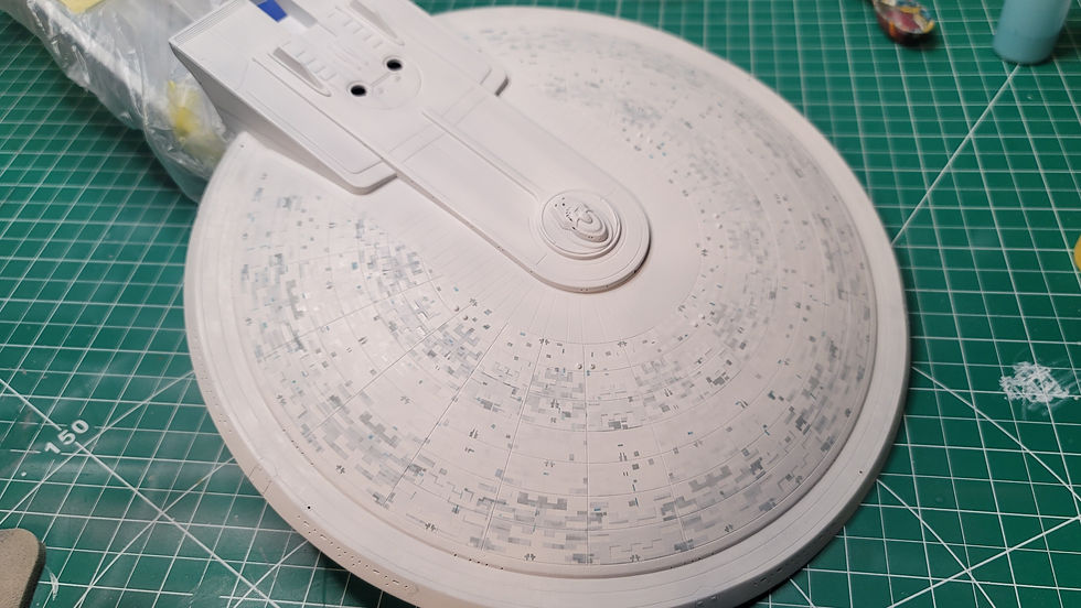
The next part is the "Horseshoe".
The files provided for the grey and blue wedges and the white pinstripes will get you super close, but they aren't precise. Feel free to mask these off yourself or draw your own pattern for the white pinstripes.
Then use the same pattern that goes around the cargo bay opening to mask off certain shapes. Paint these shapes on the horseshoe with a very light grey. I added white to the same grey used on the larger panels of the horseshoe. You can scale the file to fit to taste, I just used the same size.
Aaaaand once again paint the rest of the saucer!
For the impulse engine crystals there is a mask pattern to create the frames. Cut these out of permanent vinyl and paint them silver. You might cut out a strip of vinyl to wrap around the edge of the crystal if you'd like.

You might also like to use the railroad tracks on the large blue sections of the B and C decks to create the patterns found there. The best way to do it is to paint gloss through them.
I opted against this because I cannot cut them small enough to fit the way I want.
There are also files to paint the sensor bands around the rim. Make sure these actually line up!
Whew, the paintwork is done! Here are some images of me using the custom decals that Wiley's Model Decals made for me to add all of the pinstriping and registries around the model.
And a little highlight around the docking port!
The display base was simple, it's made out of cut acrylic that interlocks with tabs. I sanded all the joints smooth with putty and painted the base black. The inside gets white because the LCARS graphics get backlit with LED tape. To keep the top graphic removable and prevent as much light leaking around the edges, I cut styrene square tubing to size and glued it around the edges. The thing that actually holds the display rod uses telescoping brass so the rod can be lifted up and laid flat for shipping. The bottom of the base gets 4 rubber feet for stability and keeping the bottom clean.
The model is powered at 12v but the Arduino only needs 5v to operate and outputs 3.3v. So a DC to DC buck converter (the black chip with the grey rectangle) steps the voltage down from 12 to 5 for the Arduino. I then added a Toshiba TBD62783APG High-Side Source Driver Integrated Circuit to the base. This is just a bunch of transistors in a chain that takes low voltage input and outputs it to whatever voltage you supply to its Voltage In pin.
And finally the entire model is done! Check out the full gallery here and don't forget to take a look at my other builds! Please feel free to reach out and ask questions, I am always happy to share.


Comments